Welcome to The Forum SA. As a visitor you have read only access to the public content areas of this website. You will have to register as a member to access all content, post messages and network with our members. Membership is free and registering is quick and easy. You can click here to register now and become a member within minutes.
I think with this I have measured 10Amps as well and blown a 15A fuse in a perm bridge.
I think it is caused from divertered neutral current.
Basically on the grid side somewhere in there street there is a rusty/broken/high resistance Neautral cable/termination so then then the current from the neutral needs to get to the TX so it goes via earth and then finds the least path of resistance which is your N and E bridge. That is why it is only present when the grid is on.
In the UK they having huge DNC issues with gas pipes getting very hot and meassuring 30Amps on gas pipes and earth cables.
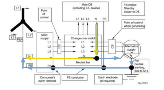
If you look at page 327, you will notice that neutral/earth bond is done at the generator before the changeover switch.
The way I see it, the bond should be done inside the inverter and only function when the inverter is in islanding mode with a built in sensor to identify if the if the bridge fails which will shut down the inverter and indicate the fault on the display.
Comments are my opinion, unless regulations are attached to support the comment. This is social media, not a court room.
Any idea when we are going to get an answer from the technical working group?
How are people registering thier SSEG if they have a permanat bond?
Originally posted by GCE
The neutral earth bridge is being taken to SANS10142-1 technical workgroup to obtain a unified answer -
The utilities are not allowing permnent neutral earth bond on there networks and it is written as such by Nersa and the bylaws
NRS 097-2-1:2017 clearly states so in Annexure B - Pasted below
Annex B � Earthing system
(informative)
NOTE SANS 10142-1 does not apply to embedded generators (i.e. connected in parallel to the utility network). Annex B is provided as minimum requirements for earthing systems until the update of SANS 10142-1.
B.1 Application of SANS 10142-1
B.1.1 General
SANS 10142-1 applies to low-voltage wiring, earthing, bonding and safety. The requirements in B.1.2 to B.1.5 relating to earthing and to neutral and earth path connections apply.
B.1.2 Neutral conductor The neutral conductor shall not be connected direct to earth or to the earth continuity conductor on the load side of the point of control (see 6.1.6 in SANS 10142-1:2012).
Comments are my opinion, unless regulations are attached to support the comment. This is social media, not a court room.
There have been many questions about whether one permanently bonds the output of an inverter and there are numerous opinions around the matter. The ECA(SA) has referred the matter to the Department of
Brilliant! So a relay it is. Glad there is something I can use to show people/clients as to why. I do use those reg numbers but coming from the ECA helps a lot to the ones that argue.
My next question which I am a bit nervous of the answer is what size relay and what size cables to bond the neutral and the earth?
Thanks GCE! I do log on and look everyone and then and get the magazine but it's been awhile.
The contactor would need to be able to handle the max possible fault current
On a 5 kw inverter , normal current would be 20Amp and depending on the inverter max possible current draw would be 1,5 times normal
I found a Sun sync practice note that I thought was interesting as it actually asks for the relay not permanent bond which is contradictory to what a couple of people on that page keep shouting - They give recommended relay sizes
Is the fault current of 20Amps being that the inverter shuts down if more than 20Amps is pulled?
I thought it would be the PSCC rating or PEFC that we would base it off.
But having that document you shared is great thank you ! Shows Sunsynk are picking up issues and finally have a document to size. I wonder when it was released as this should be huge installer knowledge which is kept quite on their side, or I live under a rock.
Still wrapping my head around fault current to a degree so if I sound dumb apologies. Rather learn and be better than keep head under a rock
PSCC ( Prospective short circuit current ) or max fault current is basically the same thing - It is the maximum possible current that might be able to flow in the circuit before the breaker trips or power source can produce.
In a 500Kva transformer the fault current is relatively large before the copper melts away and stops the current flow.
In a generator it will generally be 1,5 times the rated alternator current as anything higher will stall the diesel motor unless they stick a 1 000kw diesel motor on a 500Kw alternator
On an inverter the electronics will switch/trip the unit before the current gets out of hand
The whole DC combiner box not having MC4s, I saw you mention it before but I am not quite on the same page in terms of understanding why it's not right ?
I get the ease of disconnect to isolate and do some cool seward tester things but other than that I am not sure.
Why do you think solar panels/PV modules have MC 4 connectors and not bare wires hanging loose from the module?
I learnt the hard way, I had to upgrade a DC control box, yes I know, because of my lack of experience in the industry, I also followed the rest of the sheep.
If you dont have MC4 connectors on the ends of the cables coming down from the roof, if its a single story with a nice roof, you have to find a ladder, find the MC disconnect tool, climb on the roof, find which panels has the wires going down to the DC box then disconnect, simple if you did the install and there are only 6 modules. Don't forget the side cutter for the cable ties. If it is a double story, with a hectic angle, and the modules are 3 deep and right against the side of the roof then it becomes a much bigger task, then its safety harnesses long ladders, you get the idea.
If there was a DC isolator on the side of the building which could be locked out, then no need for MC4 connectors, you simply pull the isolator and disconnect the wires in the DC box.
Basically the leads from the roof are just an extension of the module leads, so it makes sense that they should also have MC4 connectors. From the DC control box to the inverter there is no need for MC4 connectors, why because normally people fit a double pole DC isolator in the control box and you can switch off the isolator.
Just when you thought that sounds great, there is another challenge, for example on inverters like the Sunsynk 8 kw, which has 2+2 PV connection, now when you switch off the one isolator, you still have power on the other string back feeding. If you do decide to fit one of those silly so called DC combiner boxes, you should fit 4 pole Dc isolator for string 1 and 2 and another 4 pole Dc isolator 2 and 4, otherwise someone is going to going to end up dead.
I wouldnt even consider fiddling with solar system if I hadn't taken the time to do all the research into solar that I have, it just too risky.
Originally posted by Dylboy
The whole DC combiner box not having MC4s, I saw you mention it before but I am not quite on the same page in terms of understanding why it's not right ?
I get the ease of disconnect to isolate and do some cool seward tester things but other than that I am not sure.
Sent from my CPH2197 using Tapatalk
Comments are my opinion, unless regulations are attached to support the comment. This is social media, not a court room.
2 things to note before everyone gets ahead of themselves. This information is about as valuable as others telling you that a permanent is the regulation. It means absolutely nothing until it is official.
The ECA(SA) has referred the matter to the Department of Employment and Labour and South African National Standards for deliberation and clarification from official sources and await feedback.
The onus to confirm compliance remains with the installer to verify.
Originally posted by GCE
Hi Guys
Finally have a statement that has been a long time coming from Industry
2 things to note before everyone gets ahead of themselves. This information is about as valuable as others telling you that a permanent is the regulation. It means absolutely nothing until it is official.
[FONT="]The ECA(SA) has referred the matter to the Department of Employment and Labour and South African National Standards [/FONT][FONT="]for deliberation and clarification from official sources and await feedback[/FONT][FONT="].[/FONT]
The onus to confirm compliance remains with the installer to verify.
It holds more water than a personal opinion as it comes from an Association that represents electrical contractors and was debated at length with technical reasoning behind it.
ECA will take it to SANS working group
And when I say debated at length , trust me that it was a lengthy and frustrating process
Now to get a statement out on battery placement /safety requirements
We process personal data about users of our site, through the use of cookies and other technologies, to deliver our services, personalize advertising, and to analyze site activity. We may share certain information about our users with our advertising and analytics partners. For additional details, refer to our Privacy Policy.
By clicking "I AGREE" below, you agree to our Privacy Policy and our personal data processing and cookie practices as described therein. You also acknowledge that this forum may be hosted outside your country and you consent to the collection, storage, and processing of your data in the country where this forum is hosted.

 Tweet
Tweet


Comment